


Some history of SPADIC in pictures
|
||||
|
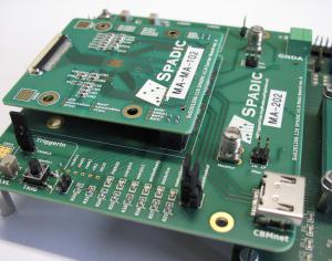
August 2012: The second SPADIC 1.0 front-end PCB. The die is directly wire-bonded to a carrier board. The carrier
board is plugged onto a small main board, which can be connected in various ways (e.g. via CBMnet
over HDMI or directly to the Susibo, as shown in the picture). The main board provides various
voltage regulators and other peripheral parts.
|
|||